Raspberry Pi Blinking LED Tutorial
From Xojo Documentation
In this tutorial, you will create a simple circuit with an LED and will then make the LED blink using a simple Xojo app.
Contents
Parts
In order to build the circuit, you'll need some parts:
- 1 ribbon cable with Raspberry Pi GPIO connectors (AdaFruit link)
- 1 cobbler (AdaFruit link)
- 1 breadboard (AdaFruit link)
- 3 jumper wires (AdaFruit link)
- 1 LED (AdaFruit link)
- 1 10k resistor (SparkFun link)
In order to make the LED blink with Xojo, you'll need to install the wiringPi library and grab the WiringPiXojo module, located here:
Examples/Platform-Specific/Linux/Raspberry Pi
Or you can download the latest version from GitHub.
Connect Ribon Cable to Pi
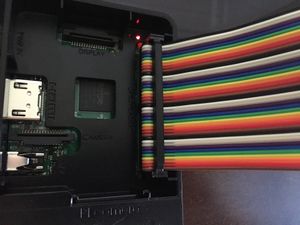
Connect the ribbon cable to the Raspberry Pi. The white/black side is typically facing the side of the Pi that does not have connectors. There is not a lot of room to work so take your time and make sure the pins are all aligned before you push it down.
Setup the Breadboard
A breadboard is the place where you will wire your circuit. The ribbon cable and cobbler are essentially used to extend the GPIO port pins to the breadboard. On the breadboard you can wire everything without soldering. You just plug things into the holes on the breadboard.
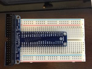
First, you'll want to plug your cobbler into the breadboard. The cobbler has to be in the center so that the left and right pins are separated by the center channel of the breadboard. In this picture, a "t-cobbler" is used and it is plugged near the top of the board to maximize available space on the board for wiring.
Carefully make sure all the pins are lined up with the holes on the breadboard and push it down. It may take a bit of force, but you want to get the cobbler to be flush with the breadboard.
The last step is to connect the cobbler to the Raspberry Pi. Plug the other end of the ribbon cable into the cobbler. It's likely the cobbler will have a slot in it so that the ribbon cable only fits in one direction.
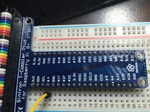
With the breadboard connected, you now have access to the pins on the GPIO port. As you can see in the photo above, this cobbler has each of the pins labelled so you can easily tell what they are for without having to count them.
Each row on the breadboard that matches up to a pin on the cobbler is "connected" to the pin on the cobbler. Any wires you connect on that row will act as if they are connected to pin on the GPIO port. For example, looking at the cobbler, you can see that the pin marked "#17" is aligned with row 6 on the cobbler.
Wire the Circuit
Now that you have the breadboard hooked up to the Raspberry Pi, you can start on building the blinking LED circuit. In this step you'll use 3 wires, 1 LED and a resistor.
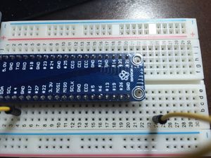
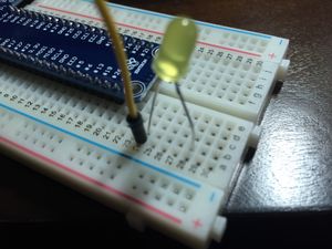
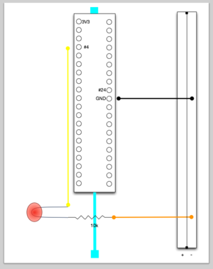
- Connect a wire to the pin marked "#4". Yellow is used in this example.
- Connect the other end of the wire to an open spot on the board away from the cobbler. Here row 24 is used.
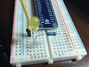
- Grab the LED. Note that one of the wires coming from the LED is longer than the other. The longer end is the positive (+) connector. Plug the long end into a hole on the breadboard adjacent to the wire (yellow) and the short end to an open row on the breadboard.
- A resistor is needed to prevent the power provided by the Pi from blowing out the LED. Take the 10k resistor and connect one end so that it is adjacent to the negative wire of the LED. Connect the other end of the resistor to an open spot on the board. If you cross over the center of the board to the other side, you can take advantage of the same row, which is what is done here.
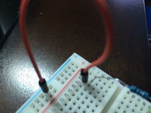
- Now connect another wire adjacent to the unconnected resistor wire. Connect this wire to the negative (-) column on the breadboard. This is usually the column on the outer edge.
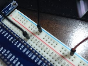
- Lastly, connect a wire from the negative column of the breadboard to a GND pin on GPIO. There are several GND pins; you can use any one that is easily reachable.
- This completes the circuit.
You can quickly test the circuit by moving the yellow wire from pin #4 to pin 3v3. This directly connects the circuit to 3.3 volt power. The LED should immediately light up. Switch it back to the #4 pin before moving on to creating the Xojo app.
Create the Xojo app
To test your circuit, you'll use a simple Xojo app that will alternate between ON (HIGH) and OFF (LOW) on pin #4. When the pin is ON (HIGH), the LED will illuminate.
- Create a new Console project and call it LEDBlinker.
- Add the GPIO module to the project.
- Add this code to the App Run event handler:GPIO.SetupGPIO
Const kLEDPin = 4 ' "#4" on the pinout
' Set the pin to accept output
GPIO.PinMode(kLEDPin, GPIO.OUTPUT)
' Blink LED every 1/2 second
While True
' Turn the pin on (give it power)
GPIO.DigitalWrite(kLEDPin, GPIO.ON)
App.DoEvents(500)
' Turn the pin off (no power)
GPIO.DigitalWrite(kLEDPin, GPIO.OFF)
App.DoEvents(500)
Wend
Make sure you've selected Linux in Build Settings and its architecture to ARM 32-bit in the Inspector and then Build the app.
Transfer and Run the Xojo app
Start your SFTP app and connect to the Raspberry Pi. Transfer the LEDBlinker folder from the Linux build folder to the Pi. On the Pi, open the Terminal (or ssh to it from your development machine). In the terminal, navigate to the location of the LEDBlinker folder and then CD to the folder:
cd LEDBlinker
Run the app:
sudo ./LEDBlinker
Normally sudo is needed to access GPIO. The GPIO.SetupGPIOSys method does provide access to some GPIO functionality without requiring sudo.
The LED should start blinking. To stop the app, press Control-C.
Note that if you press Control-C while the LED is on, it will remain on.
Starting with Raspbian Jessie, you no longer have to use sudo to access GPIO. In order to not require sudo, you have to first set an environment variable before you run the app:
export WIRINGPI_GPIOMEM=1
The Xojo project is included with the Xojo examples and is located here:
Examples/Platform-Specific/Linux/RaspberryPi
Video
Watch the companion step-by-step video: https://youtu.be/Lqhiazf_-ns
Circuit Diagram
Here is a circuit diagram for reference:

