Getting started with the Arduino Uno WiFi Rev2
The Arduino Uno WiFi Rev2 is an Arduino Uno with an integrated WiFi module. The board is based on the Microchip MEGA4809 with an ESP32 u-blox NINA-W13 WiFi Module integrated. The NINA-W13 Module is a self contained SoC with integrated TCP/IP protocol stack that can give access to your WiFi network (or the device can act as an access point).
The Arduino Uno WiFi Rev2 is programmed using the Arduino Software (IDE), our Integrated Development Environment common to all our boards and running both online and offline. For more information on how to get started with the Arduino Software visit the Getting Started page.
On this page... (hide)
Use your Arduino Uno WiFi Rev2 on the Arduino Web IDE

All Arduino boards, including this one, work out-of-the-box on the Arduino Web Editor, no need to install anything.
The Arduino Web Editor is hosted online, therefore it will always be up-to-date with the latest features and support for all boards. Follow this simple guide to start coding on the browser and upload your sketches onto your board.
Use your Arduino Uno WiFi Rev2 on the Arduino Desktop IDE
If you want to program your Arduino Uno WiFi Rev2 while offline you need to install the Arduino Desktop IDE. Full instructions on how to install it can be found in our Getting Started page.
Installing Drivers for the Uno WiFi
OSX
No drivers are needed for the Arduino UNO WiFi Rev. 2 on macOSX.
Windows (tested on XP, 7, Vista and 10)
At this point of this Getting Started guide you already have installed the drivers together with the Arduino Software (IDE) and the board will be recognized automatically.
Linux
There is no need to install drivers for Ubuntu 10.0.4 and later, but make sure port 5353 is not being blocked by a firewall.
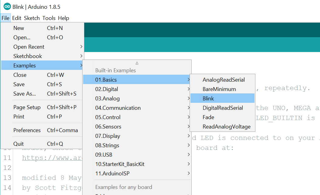
Open your first sketch
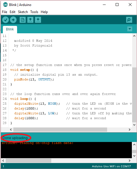
Open the LED blink example sketch: File > Examples >01.Basics > Blink.
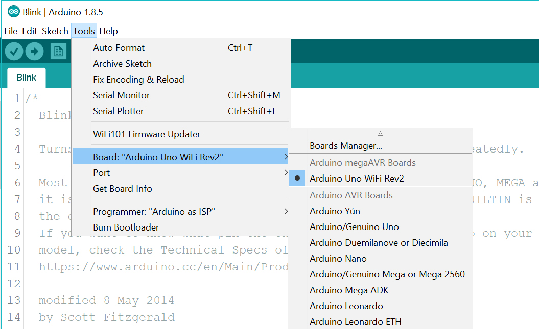
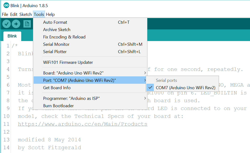
Select your board type and port
You'll need to select the entry in the Tools > Board menu that corresponds to your Arduino Uno WiFi Rev2 board.
Select the serial device of the board from the Tools | Serial Port menu. This is likely to be COM3 or higher (COM1 and COM2 are usually reserved for hardware serial ports). To find out, you can disconnect your board and re-open the menu; the entry that disappears should be the Arduino Uno WiFi Rev2 board. Reconnect the board and select that serial port.
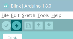
Upload the program
Now, simply click the "Upload" button in the environment.
Wait a few seconds - you should see the RX and TX LEDs on the board flashing. If the upload is successful, the message "Done uploading." will appear in the status bar.
A few seconds after the upload finishes, you should see the on-board LED start to blink. If it does, congratulations! You've gotten your Uno WiFi board up-and-running for the USB programming. If you have problems, please see the troubleshooting suggestions.
Tutorials
Now that you have set up and programmed your Uno WiFi board, you may find inspiration in our Project Hub tutorial platform, or have a look to the tutorial pages that explain how to use the various features of your board. We suggest that you visit the WiFi Nina Library page that explains the network functions of this board.
Please Read...
This board uses the new Microchip MEGA4809 microcontroller that has a different memory layout compared to the usual ATmega 328P. You now have 48K of Flash memory, 6K of RAM and 256 bytes of EEPROM, therefore you have more Flash and more memory than the Arduino UNO (16K Flash and 2K RAM). The programming of the MEGA4809 happens through an ATmega 32U4 programmed with the mDBG code and creates a virtual COM port when connected to a PC.
Serial ports
The Arduino Uno WiFi Rev. 2 has 3 hardware serial ports. Serial is connected to the USB interface, Serial1 is connected to Pin 0 (RX) and 1 (TX), Serial 2 is connected to the u-blox NINA-W13 module. This allows the usage of pins 0 and 1 without issues: on the original Arduino UNO, the usage of Pins 0 and 1 disrupts the sketch upload.
SPI
The SPI interface is available on the ICSP connector with the usual layout for MISO, MOSI, SCK and CS. The IMU and the WiFi module are connected to the SPI bus and have individuale and dedicated pins for Chip Select (CS)
Analog
The new core has 5 PWM pins and the pin 11 doesn't support PWM. The resolution of the 6 A/D pins is the usual, with 10 bits and values from 0 to 1023.
RGB LED
Close to the Nina module and the ICSP connector there is a square RGB SMD LED. This LED is directly connected to the NINA-W13 WiFi module and it is driven by the module itself. It will be used for future applications and developments.
Integrated IMU
On the SPI bus, with a dedicated CS connection (pin D30 or SPIIMU_SS) and a dedicated interrupt pin (SPIIMU_INT), the Arduino UNO WiFi Rev.2 has a LSM6DS IMU with 3-axis accelerometer and 3-axis gyroscope. This chip made by ST Microelectronics is a standard component already supported by many libraries; you can choose between the available ones in our library manager using LSM6DS keyword.
Interrupts
The new MEGA4809 microcontroller allows you to attach any digital pin to an interrupt, therefore you may have as many Interrupt Service Routines (ISR) as the available digital pins. You still define the interrupts with the usual function attachInterrupt(digitalPinToInterrupt(pin), ISR, mode);. Please refer to the attachInterrupt() page for further details.
Note: the WiFi antenna built in in the U-blox NINA-W13 module is made for embedded products and should NOT be touched. Applying pressure or force on it could cause damage. Be very careful when you detach shields on this board because you may pull the WiFi antenna.

Last revision 2018/10/30 by AR
The text of the Arduino getting started guide is licensed under a
Creative Commons Attribution-ShareAlike 3.0 License. Code samples in the guide are released into the public domain.
