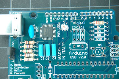
In order to test the USB chip, solder the components that support it to the board next. They are as follows:
- R2, 10Kohms (brown-black-orange-gold)
- R3, 27 ohms (red-purple-black-gold)
- R4, 27 ohms (red-purple-black-gold)
- R5, 1.5Kohms (1K5) (brown-green-red-gold)
- R6, 470 ohms (yellow-purple-brown-gold)
- C4, 100nF (0.1uF) (104)
- C8, 100nF (0.1uF) (104)
- C9, 100nF (0.1uF) (104)
- X1, USB connector
- R8, 220 ohms (red-red-brown-gold)
- PWR_LED (make sure long end goes to + hole)
- SV1, 3 pin header (make sure they are perpendicular to the board)
- OSC, 6MHz oscillator, 3-pin
After soldering these parts, your board will look like this:

Now you can test to see if the chip works (partially). Install the FTDI FT232BM USB drivers on your computer, and put the shorting block across the two header pins of SV1 closest to the USB connector. This will allow the board to draw power from the USB connection. Plug your board into a USB port of your computer. The LED should light up. When you open Arduino and check the serial port list, you should have a new serial port. On OSX, it's called "USBserial-" followed by a hexadecimal number.
Once that's done, you're ready to solder the rest of the components.
