Arduino LCD playground | KS0108 Graphics LCD library
KS0108 Graphics LCD library
glcd-arduino (GLCDv3) is an unofficial Arduino library that supports Graphic LCDs (GLCD) that use the KS0108 (or equivalent) chip.
NOTICE: GLCDv3 is no longer recommended
GLCDv3 development has been idle since ca. 2012 and the authors have not done an official code release since Dec 2011. The GLCDv3 library does not work on newer arduino boards and no longer builds on newer IDEs The GLCDv3 library has reached end of life.
The primary author of GLCDv3 has moved on to openGLCD. OpenGLCD provides greater functionality and wider hardware support, has a GLCDv3 compatibility mode, and uses GLCDv3 library wiring.
Also, the google code repository site where the GLCDv3 library was hosted is no longer supported by Google. Projects on that site have been archived but capabilities of the Google Code site are slowly being turned off and removed. At some point the Google Code site will probably be taken down completely.
Therefore, GLCDv3 is no longer recommended for use.
The GLCDv3 library contains a notice on its main Google Code project page: glcd-arduino But since Google Code is slowly disappearing, I have reproduced it here:
This library is no longer being maintained by the authors and has not been updated since December 2011. This library does not work with newer Arduino IDEs like the latest 1.0.x releases as well as 1.6.0 IDE and beyond since the newer IDEs use updated AVR gcc tools and GLCDv3 library uses code which is not compatible with the newer AVR gcc tools.
GLCDv3 alternative libraries:
If you are ok with a GPL 3.0 licensed library (your project is open source) openGLCD is an alternative which is compatible with GLCDv3 and is being maintained.
https://bitbucket.org/bperrybap/openglcd/
u8glib is another alternative and is licensed under the new bsd license:
https://code.google.com/p/u8glib/
Additional information can be found here: http://forum.arduino.cc/index.php?topic=56705.msg1509585#msg1509585
The remainder of this page is about GLCDv3 for those that would like to continue to use it.
The last version of the glcd-arduino library (v3) can be found here: glcd library downloads. The library includes example
sketches and a readme.txt file to explain the basics of adding a library as well as extensive documentation.
For the latest and most complete documentation refer to the html documentation included in the library download.
(click on glcd/doc/GLCDref.htm to bring up HTML documentation)
Version 3 (Officially released June 2012) Source code and related downloads can be found on the Google code project: glcd-arduino
glcd-arduino has the following features:
- Support for Arduino 1.x (still works with pre 1.x IDEs)
- Support for Mega 2560, Sanguino and Teensy boards
- Easier pin assignment. Any pin can be assigned to any glcd function.
- Accurate/Consistent font rendering of any font size on any pixel location.
- User definable text areas
- Up/Down text scrolling
- Circle functions
- Additional example and demo sketches including a diagnostic sketch
- Fully search-able documentation in HTML format
- Pins can optionally be assigned by AVR port and bit instead of Arduino pin number.
- Supports fixed width fonts that provides up to 8 x 21 character display with the supplied system font.
- CursorTo method to position the cursor to a given font location (fixed width fonts only)
- DrawBitmap function to display bitmap images stored in Flash memory. A Processing utility is provided in the download to convert a monochrome bitmap file to a header file that stores the image in flash for use by the DrwBitmap method.
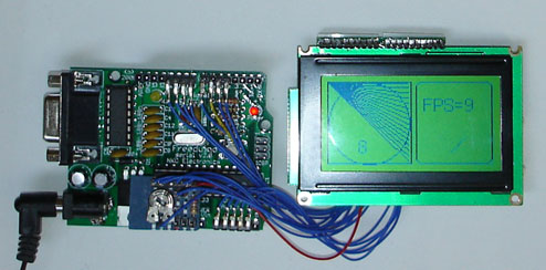
Picture of a test sketch running on a max232 Freeduino board with a low cost GLCD panel
The library is based on the excellent ks0108 graphics routines written and copyright by Fabian Maximilian Thiele. The site link in his code does not respond but you can obtain a copy of his original work in the download section at the end of this article.
The code here has been converted to an Arduino library, has more flexibility in port addressing and improvements in I/O speed. The interface has been made more Arduino friendly and some convenience functions added. The method naming is mostly unchanged to facilitate porting of code written for the original version. Some methods now have default arguments to make them easer to use.
The test sketch included in the download demonstrates many of the capabilities of the library and if you start with this and use the default Arduino pin assignments, it is a good way to make sure that everything is working before you customize your configuration. Here is a simplified version of the example sketch in the download:
Example GLCD sketch
  #include <ks0108.h>  // library header
  #include <Arial14.h>  // font definition for 14 point Arial font.
  #include "SystemFont5x7.h"   // system font
  #include "ArduinoIcon.h"     // bitmap
  unsigned long startMillis;
  unsigned int iter = 0;
void setup(){
  GLCD.Init(NON_INVERTED);   // initialise the library
  GLCD.ClearScreen();
  GLCD.DrawBitmap(ArduinoIcon, 32,0, BLACK); //draw the bitmap at the given x,y position
  delay(3000);
  GLCD.ClearScreen();
  GLCD.SelectFont(System5x7);       // select fixed width system font
}
void loop(){ // run over and over again
  startMillis = millis();
  while( millis() - startMillis < 1000){ // loop for one second
    GLCD.DrawRect(0, 0, 64, 61, BLACK); // rectangle in left side of screen
    GLCD.DrawRoundRect(68, 0, 58, 61, 5, BLACK);  // rounded rectangle around text area
    for(int i=0; i < 62; i += 4)
      GLCD.DrawLine(1,1,63,i, BLACK);  // draw lines from upper left down right side of rectangle
    GLCD.DrawCircle(32,31,30,BLACK);   // draw circle centered in the left side of screen
    GLCD.FillRect(92,40,16,16, WHITE); // clear previous spinner position
    GLCD.CursorTo(5,5);               // locate curser for printing text
    GLCD.PrintNumber(++iter);         // print current iteration at the current cursor position
  }
  // display number of iterations in one second
  GLCD.ClearScreen();               // clear the screen
  GLCD.CursorTo(13,2);              // positon cursor
  GLCD.Puts("FPS= ");               // print a text string
  GLCD.PrintNumber(iter);           // print a number
 }
Functional overview:
This is a list of functions supported by the library.
(Refer to the included HTML library documentation for the latest and most complete documentation)
 GLCD.Init(invert) initialize the library for normal or inverted drawing. If invert is false,
  drawing sets pixels, if true pixels are cleared when drawn (see also SetInverted method)
 GLCD.GotoXY(x,y) locate the graphic cursor at positions x and y, 0,0 is upper left corner
 GLCD.ClearScreen() clear the LCD screen
 // Graphic Drawing Functions (color WHITE clears pixels, BLACK sets pixels)
 GLCD.DrawCircle(x, y, radius, color) draw circle with center at x,y
 GLCD.DrawLine(x1,y1,x2,y2,color) draw line from x1,y1 to x2,y2
 GLCD.DrawVertLine(x, y, length, color) draw vertical line
 GLCD.DrawHoriLine(x, y, length, color) draw horizontal line
 GLCD.DrawRect(x, y, width, height, color) draw rectangle
 GLCD.DrawRoundRect(x, y, width, height, radius, color) as above with rounded edges
 GLCD.FillRect(x, y, width, height, color) draw filled rectangle
 GLCD.InvertRect(x, y, width, height) invert pixels within given rectangle
 GLCD.SetInverted(invert) set drawing mode to inverted
 GLCD.SetDot(x, y, color); draw a dot in the given color at the given location
 GLCD.DrawBitmap(bitmap, x, y, color); draw the bitmap at the given x,y position
 // Font Functions
 GLCD.SelectFont(font, color ) select font, defaults color to black if not specified
 GLCD.PutChar(character) print given character to screen at current cursor location
 GLCD.Puts(string) print given string to screen at current cursor location
 GLCD.Puts_P(string) print string from program memory to screen at current cursor location
 GLCD.PrintNumber(number) print the decimal value of the given number at current cursor location
 GLCD.CursorTo(x, y); // 0 based coordinates for fixed width fonts (i.e. the supplied system font)
Note: valid colors are BLACK (sets pixels) or WHITE (clears pixels)
Wiring and Configuration:
In v3 there are 3 types of configuration:
- Library
- Panel
- Pin
Each type of configuration is handled by separate configuration files.
The library configuration is handled by glcd/glcd_Config.h The library configuration determines things like panel type, as well as a few other options. It is the master configuration file.
The panel configuration is used to configure things that are specific to a particular glcd panel like the geometry of the display, the chip select lines, and the low level timing for the panel. The glcd_Config.h library configuration file specifies which panel configuration file to use.
The pin configuration is used to assign pins. A given panel configuration will automatically determine which pin configuration file to use based on which board type is being used in the IDE.
Pin assignments are contained in the appropriate pin configuration header file in glcd/config for the supported controller chips. These controller types are supported in the current version:
- ks0108_arduino.h <- this is for ATmega168 and ATmega328 boards
- ks0108_mega.h <- for the Arduino Mega (ATmega1280/2560)
- ks0108_Sanguino.h <- for Sanguino (ATmega644)
- ks0108_Teensy.h <- for Teensy/Teensy++
See the readme file, glcd/glcd_Config.h and included HTML documentation supplied with the download for more details on configuration.
It is suggested that you wire up the panel using the default pin assignments. This diagram shows how panels should be connected using the default pin assignments in the distributed library.
IMPORTANT NOTE:
The connections to the glcd module must be soldered. While tempting to push wires or a 20 pin header into the holes without soldering, that will not create proper electrical connections.
| GLCD Panel Pinouts | |||||||
| Arduino 168 | Mega | Function | Pinout A | Pinout B | Pinout C | Pinout D | Comments |
| 5V | 5V | +5 volts | 1 | !2! | !2! | 4 | |
| Gnd | Gnd | GND | 2 | !1! | !1! | 3 | |
| n/a | n/a | Vo (Contrast in) | 3 | 3 | 3 | 5 | Connect to Wiper of contrast pot (Middle pin) |
| 8 | 22 | D0 | 4 | 7 | 7 | 9 | |
| 9 | 23 | D1 | 5 | 8 | 8 | 10 | |
| 10 | 24 | D2 | 6 | 9 | 9 | 11 | |
| 11 | 25 | D3 | 7 | 10 | 10 | 12 | |
| 4 | 26 | D4 | 8 | 11 | 11 | 13 | |
| 5 | 27 | D5 | 9 | 12 | 12 | 14 | |
| 6 | 28 | D6 | 10 | 13 | 13 | 15 | |
| 7 | 29 | D7 | 11 | 14 | 14 | 16 | |
| 14 (alog0) | 33 | CSEL1 | 12 | 15 | 16 | 1 | Chip 1 select |
| 15 (alog1) | 34 | CSEL2 | 13 | 16 | 15 | 2 | Chip 2 select |
| Reset | 14 | 17 | 17 | (see Reset pin note below) | |||
| 16 (alog2) | 35 | R_W | 15 | 5 | 5 | 7 | Read/write |
| 17 (alog3) | 36 | D_I | 16 | 4 | 4 | 6 | Data/Instruction (aka RS) |
| 18 (alog4) | 37 | EN | 17 | 6 | 6 | 8 | Enable |
| n/a | n/a | Vee/Vout (Contrast out) | 18 | 18 | 18 | connect to one leg of 10k or 20k pot | |
| n/a | n/a | Backlight +5 | 19 | 19 | 19 | 100 to 330 ohm resistor to +5v | |
| Gnd | Gnd | Backlight Gnd | 20 | 20 | 20 | ||
| n/a | n/a | n/a | n/a | n/a | n/a | n/a | connect other leg of contrast pot to Gnd |
Reset Function Note:
If the IDE fails to upload the Arduino when the glcd module's reset line is attached to the Arduino board's reset pin, see the troubleshooting guide below for remedies.
Pinout A panels:
- HDM64GS12L-4
- Crystalfontz CFAG12864B (tested by biomed)
- Specifically for CFAG12864B-YYH-N model, pin 18 is NC (this model doesn't have built-in negative voltage generator). As a result, pin 3 should still be connected to center of pot (20k) with one end goes to Arduino's +5v (not GND) and the other goes to -5V provided by external power supply (not pin 18). Also, CSEL1 and CSEL2 should be swapped, otherwise half left and half right of the whole image is reversed.
- Sparkfun LCD-00710CM (tested by biomed)
- NKC Electronics LCD-0022 (tested by NKC Electronics)
- Longtech LGM128164H (tested by mr_lanza)
Pinout B panels:
- HDM64GS12L-5
- Lumex LCM-S12864GSF (tested by jowan)
- Futurlec BLUE128X64LCD (tested by tyggerjai)
- AZ Displays AGM1264F (tested by santy)
- Displaytech 64128A BC (tested by Udo Klein)
- Adafruit GLCD (Leave RESET pin disconnected or you may experience upload problems) (tested by Things)
- DataVision DG12864-88 (tested by wglover)
- Topway LM12864LDW (tested by zandaa)
- Satistronics RT12864J-1 (tested by doublet)
- Digitron SG12864J4 (also appears to need RESET disconnected for uploads)
- Unknown manufacturer QY-12864F (tested by SphiNx)
- Unknown manufacturer TM12864L-2 (tested by frantorres)
- Unknown manufacturer 12864J-1 (tested by pixelk)
- Huahong Technology Ltd LMG12864 (LMG-SSC12A64DRY(-H) variant, yellow green backlight, black on green) (tested by yxskaft)
- Sure Electronics DE-LM105 (tested by imode)
- Wide.hk "LCD Shield Pro + GLCD 128x64 LCD" (tested by universam) 6-way Keypad shortens CS1 (A0) to ground!
- NAN YA Plastics Corp LMC97S005C (tested by serisman)
- Unknown manufacturer SYT-12864 (tested by serisman)
Pinout C panels:
- Shenzhen Jinghua Displays Co Ltd. JM12864 (tested by macpod)
- Vo (pin 3) should be left disconnected. The pot on the display controls contrast
- Backlight LED may already have resistors added.
Pinout D panels:
- Various 192 x 64 displays:
| Brand | Model | Chip | Contrast |
| Wintek- Cascades | WD-G1906G | KS0108B | -7.5 to -10v |
| Wintek - GEN | WD-G1906G | KS0108B | -7.5 to -10v |
| Wintek | WD-G1906G | S6B0108A | -9.5 to -12v |
| TECDIS | Y19061 | HD61202 | -7.5 to -10v |
| Varitronix | MGLS19264 | HD61202 | -8.5 to -10.5v |
- The contrast voltage is negative with respect to ground.
- Backlight is 4.7v requiring 10-12 ohm resistor from +5v.
- The ks0108_Manual_Config.h needs to be used and modified as below.
- define DISPLAY_WIDTH 192
- define DISPLAY_HEIGHT 64
and
- elif glcd_CHIP_COUNT == 3
- define glcd_CHIP0 glcdCSEL1,LOW, glcdCSEL2,LOW
- define glcd_CHIP1 glcdCSEL1,LOW, glcdCSEL2,HIGH
- define glcd_CHIP2 glcdCSEL1,HIGH, glcdCSEL2,LOW
(You are welcome to add other panels to the above lists that are tested and working with this library. But if you add a new panel pinout type column to the table i.e. E, F, G, etc... PLEASE, PLEASE add them to the end using the next available letter and do not shift existing letters around.)

This diagram shows wiring of the common type A panel. Check to see how your panel datasheet matches the connector assignments before wiring up. Take particular care that the +5v and ground connections are correct!
Wiring up the external components:
Most GLCD panels require an external preset pot to set the LCD working voltage (contrast) and a fixed resistor to limit the current in the backlight. The datasheet for your panel should provide specific information on the wiring and choice of components. A suggestion for wiring these up is to use a small piece of strip-board with header pins for 5V, ground and Reset providing connection to the Arduino. See the diagram above for layout.
Contrast Pot NOTE:
Play close attention for how to wire up the contrast pot. ks0108 modules do not wire up their contrast pot the same way as a typical hd44780 lcd. A hd44780 typically hooks its contrast pot legs to +5v and GND.
On a ks0108, the pot, which is typically between 10-20k, is used to create a varying negative voltage from Vee up to GND that is used to feed to the Vo input signal.
In order to do this, one leg of the pot needs to hook to ground, one leg needs to hook to the Vee negative voltage output pin and then the wiper (middle pin of the pot) will have the variable voltage output that can be fed to the Vo contrast control input pin.
Changing the Arduino pin assignments:
The KS0108 chip needs lots of pins. 8 data pins and 5 command pins are required in addition to the power connections. Ideally the command pins should all be on one port and all the data pins together on another. In practice this is not easy to do on a standard arduino.
Starting with glcd v3, pin assignment is much more flexible as any glcd function or data pin can be assigned to any Arduino pin. If you split data pins across ports the code will run slightly slower, but for all but the most speed critical graphic applications its not significant. To change pin assignments you must modify the appropriate pin configuration file in the glcd/config directory (ks0108.h when using a m328 based arduino). Find the section in the file that begins:
 /********************************************************/
 /* Configuration for assigning LCD bits to Arduino Pins */
 /********************************************************/
You will see the defines for the data pins and the five control pins with their default pin assignments:
        Name    Arduino pin number
 #define glcdData0Pin        8
 #define glcdData1Pin        9
 #define glcdData2Pin        10
 #define glcdData3Pin        11
 #define glcdData4Pin        4
 #define glcdData5Pin        5
 #define glcdData6Pin        6
 #define glcdData7Pin        7
 #define glcdCSEL1           14 (Analog pin 0)
 #define glcdCSEL2           15 (Analog pin 1)
 #define glcdRW              16 (Analog pin 2)
 #define glcdDI              17 (Analog pin 3)
 #define glcdEN              18 (Analog pin 4)
Any of these data pins and glcd functions can be assigned to any pin (as long as its not used by something else) Here are the pin/port mappings for the Arduino m328 processor:
- Port B 8-13
- Port C 14-19 (the analog pins)
- Port D 0-7 (note 0 and 1 are used by hardware serial)
While any Arduino pin can can be used for any glcd data pin, using Arduino pins that are all in the same port and that are in consecutive bit order will give slightly higher performance. The default pin assignments for the glcd data pins are assigned to take advantage of this optimization.
An example of remapping a pin might be to change glcdEN to use some other pin rather than 18 to allow using i2c on a m328 based board.
Troubleshooting
No pixels visible on the display
- Check +5v and Gnd connections between Arduino and GLCD panel
- Check that all data and command pins are wired correctly
- Check contrast voltage (typically between -3 and -4 volts) on contrast-in pin of LCD panel. While the sketch is operating, try gradually adjusting the pot through its range. Some displays are very sensitive to this setting.
- Check sketch has compiled ok and downloaded to the arduino.
Left and right side of image reversed
- swap CSEL1 and CSEL2 wires (or swap pin assignments in header file)
Display garbled
- check all data and command pins are wired correctly and that these match the setting in the header file.
Sketch upload not working
- Try the glcd with nothing connected to its reset line
- Try connecting the glcd reset line to vcc
- enable the library software reset functionality
GLCD reset pin NOTE:
The Arduino autoreset circuit is quit fragile. Depending on the particular Arduino board and glcd module, connecting the glcd module to the Arduino board reset line may interfere with the Arduino board's autoreset circuit. Most glcds will reset on power up so the glcd reset line can be left unconnected. Most of the remaining others will work when their reset line is connected to vcc. A small fraction of the glcds out there will need a reset pulse. For those that need a reset pulse and connecting the glcd to the arduino reset line causes the autoreset on the aruduino board to fail, the library must be used to reset the glcd which requires another Arduino pin. In order to enable this functionality edit the pin configuration file and uncomment the line that looks like this:
// Reset Bit - uncomment the next line if reset is connected to an output pin //#define glcdRES 19 // Reset Bit
And then connect the Arduino pin specified by glcdRES to the glcd module's reset pin.
Still having problems, see the forum discussion links below.
On using and modifying libraries
Create your own fonts and icons
There is a free java application available that can convert any of your PC fonts for use with this library. The software is called FontCreator2 and it can produce a header file that stores font definitions in program memory when included in your sketch. See the included HTML documentation for more information about this as well as some web site links for obtaining additional fonts.
Embeding images in your firmware
A Processing sketch is provided in the download that converts bmp images to files that can be used by the library to display the image on the LCD. See the documentation in the download for more information.
Downloads:
- Hantronix Graphics LCD datasheets
- Spec sheet for the KS0108B chip
- FontCreator2 software to create fonts and symbols for use with this library
- Fabian Maximilian Thiele's original GLCD code
- Mini Interative Interface Toolkit Library - extensive GUI Menu library for GLCD
Questions, comments and suggestions on the library and documentation
ks0108/glcd v2 (read-only) Forum discussion
glcd v3 Forum discussion
glcd v3 google code page
