LedControl
a Arduino library for the MAX7221 and MAX7219
These two chips provide an easy way to control either an array of 64 LEDs or up to 8 digits of 7-segment displays. A detailed description of the hardware and a schematic can be found here.
As a teaser here is a picture of my rather crappy (but working) testbed...
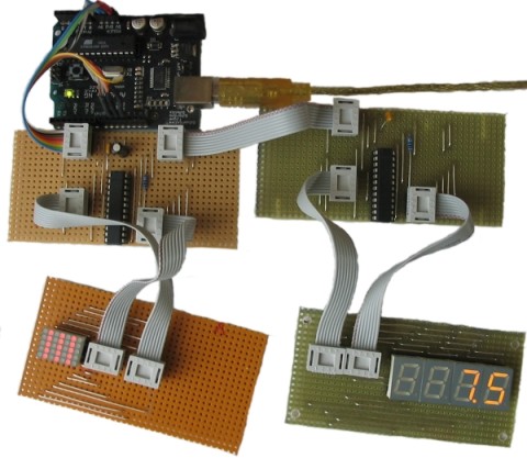
Table of contents
- Creating a LedControl
- Clearing the display
- Controlling a Ledmatrix
- Controlling 7-Segement displays
- Commented demos for the library
- Source code and download
- Revision history
The LedControl library
There is already a library and a lot of code-examples for the Arduino and the MAX72XX available, but the focus had always been on controlling LEDs laid out in some sort of rectangular matrix. I use the MAX72XX to drive 7-segment displays, so I wanted a function to display numbers (decimal and hexadecimal) and also the limited set of alphanumeric characters that make (visual) sense on this kind of displays. But the library also provides a basic set of functions by which either individual or groups of LEDs can be switched on and off.
Creating a LedControl
All the libraries API-functions are called through a variable of type LedControl which you have to create inside your projects code.
A typical code for library initialization will look like this :
/* We start by including the library */
#include "LedControl.h"

/*
 * Now we create a new LedControl.
 * We use pins 12,11 and 10 on the Arduino for the SPI interface
 * Pin 12 is connected to the DATA IN-pin of the first MAX7221
 * Pin 11 is connected to the CLK-pin of the first MAX7221
 * Pin 10 is connected to the LOAD(/CS)-pin of the first MAX7221
 * There will only be a single MAX7221 attached to the arduino
 */
LedControl lc1=LedControl(12,11,10,1);
The first step is obvious. We have to include the LedControl-library.
Then we create an instance of type LedControl through which we talk to the MAX72XX devices. The initialization of an LedControl takes 4 arguments. The first 3 arguments are the pin-numbers on the Arduino that are connected to the MAX72XX. You are free to choose any of the digital IO-pins on the arduino, but since some of the pins are also used for serial communication or have a led attached to them its best to avoid pin 0,1 and 13. I choose pins 12,11 and 10 in my example. The library does not check the pin-numbers to be valid in any way. Passing in something stupid (pin 123??) will break your app.
You don't have to initialize the pins as outputs or set them to a certain state, the library will do that for you.
The fourth argument to LedControl(dataPin,clockPin,csPin,numDevices) is the number of cascaded MAX72XX devices you're using with this LedControl. The library can address up to 8 devices from a single LedControl-variable. There is a little performance penalty implied with each device you add to the chain, but amount of memory used by the library-code will stay the same, no matter how many devices you set. Since one LedControl cannot address more than 8 devices, only values between 1..8 are allowed here.
Here is the prototype for a new LedControl-instance:
/*
 * Create a new controller
 * Params :
 * int dataPin    The pin on the Arduino where data gets shifted out
 * int clockPin   The pin for the clock
 * int csPin      The pin for selecting the device when data is to be sent
 * int numDevices The maximum number of devices that can be controlled
*/
LedControl(int dataPin, int clkPin, int csPin, int numDevices);
If you need to control more than 8 MAX72XX, you can always create another LedControl-variable that uses 3 different pins on your Arduino board.
The only thing you have to do is to initialize another LedControl
/* we have to include the library */
#include "LedControl.h"

// Create a LedControl for 8 devices...
LedControl lc1=LedControl(12,11,10,8);

// ... and another one. Now we control 1024 LEDs from an Arduino, not bad!
// Note : the second one must use different pins!
LedControl lc2=LedControl(9,8,7,8);
There is no way to read the pin-numbers from your code, but there is a function that requests the maximum number of devices attached to an LedControl. This can be very handy when you want to loop over the full list of MAX72XX devices attached. Here is a piece of code that switches all of the MAX72XX-devices from power saving mode into normal operation. I'll think you'll get the idea even though we haven't talked about the shutdown(addr) function yet...
#include "LedControl.h"

// Create a new LedControl for 5 devices...
LedControl lc1=LedControl(12,11,10,5);

void setup() {
  for(int index=0;index<lc1.getDeviceCount();index++) {
      lc1.shutdown(index,false);
  }
}
We iterate over the list of devices by an index that runs from 0 to getDeviceCount()-1. That would be 0 to 4 in this piece of code. The index is the address of each device. This address will be the first argument of every function that sets a feature or a new (Led-)value on a device.
Keep in mind that getDeviceCount() returns the number of devices attached, but the address of an device starts at 0 for the first one, 1 for the second one,.. getDeviceCount()-1 for the last one. Here is the prototype of the function:
/*
 * Gets the maximum number of devices attached to this LedControl.
 * Returns :
 * int   the number of devices attached to this LedControl
*/
int LedControl::getDeviceCount();
Power saving mode
LEDs consume quite a lot of energy when they are lit. For battery operated devices you'll definitely want to save power by switching the whole display off, when the user does not need it. A special command sequence can put the MAX72XX into shutdown mode.
The device will switch off all the LEDs on the display, but the data is retained. You can even continue to send new data during shutdown mode. When the device is activated later on, the new data will appear on your display. Here is an example for an invisible countdown on a 7-segment display:
//create a new device
LedControl lc=LedControl(12,11,10,1);

void countDown() {
  int i=9;
  lc.setDigit(0,(byte)i,false);
  //now we see the number '9'
  delay(1000);
  //switch the display off ...
  lc.shutdown(0,true);
  //and count down silently
  while(i>1) {
    //data is updated, but not shown
    lc.setDigit(0,(byte)i,false);
    i--;
    delay(1000);
  }
  //when we switch the display on again we have already reached '1'
  lc.shutdown(0,false);
  lc.setDigit(0,(byte)i,false);
}
Here is the prototype for method LedControl.shutdown(addr)
/*
 * Set the shutdown (power saving) mode for the device
 * Params :
 * int addr   The address of the display to control
 * boolean b  If true the device goes into power-down mode. If false
 *            device goes into normal operation
*/
void shutdown(int addr, bool b);
Please note that the MAX72XX is always in shutdown mode when the Arduino is powered up.
Limiting the number of digits (ScanLimit)
(This is a kind of experts feature not really needed by most users of the library. Since the library initializes the MAX72XX to safe default values, you don't have to read this section in order to make your hardware work)
When a new LedControl is created it will activate all 8 digits on all devices. Each lit digit will be switched on for 1/8 of a second by the multiplexer circuit that drives the digits. If you have any reason to limit the number of scanned digits, this is what happens : The LEDs get switched on more frequently, and therefore will be on for longer periods of time. Setting the scan limit to 4 would mean that a lit Led is now switched on for 1/4 of a second, so the MAX72XX has to provide the current on the segment-driver for a longer period of time.
You should read the relevant section of the MAX72XX datasheet carefully! Its actually possible to kill your MAX72XX by choosing a bad combination of the resistor RSet that limits the current through the LEDs and the number of digits scanned by the device.
The only reason to tweak the scanlimit at all, is that the display looks too dark. But this is most likely due to the fact that you haven't raised the intensity on startup. Anyway, here's the prototype of setScanLimit() for those who need it:
/*
 * Set the number of digits (or rows) to be displayed.
 * See datasheet for side effects of the scanlimit on the brightness
 * of the display.
 * Params :
 * int addr  The address of the display to control
 * int limit The number of digits to be displayed
 * Only values between 0 (only 1 digit) and 7 (all digits) are valid.
 */
void setScanLimit(int addr, int limit);
Setting display brightness
There are three factors that determine the brightness of your display.
- the value of resistor
RSetwhich limits the maximum current going through the LEDs. - the scan limit of the display. (If you read the section, you already know that I'd recommend to leave this option its safe default.)
- and a command that allows the brightness of the LEDs to be controlled from software.
The setIntensity(int addr, int intensity) method lets you control brightness in 16 discrete steps. Larger values make the display brighter up to the maximum of 15. Values greater than 15 will be discarded without changing the intensity of the LEDs.
You might be surprised to find out that an intensity of zero will not switch the display completely off, but we already know how to do this with the shutdown()-function.
/*
 * Set the brightness of the display.
 * Params:
 * int addr      the address of the display to control
 * int intensity the brightness of the display.
 *               Only values between 0(darkest) and 15(brightest) are valid.
*/
void setIntensity(int addr, int intensity);
Device initialization
When a new LedControl is created the library will initialize the hardware with ...
- the display blanked
- the intensity set to the minimum
- the device to be in power saving mode
- the maximum number of digits on the device activated
A blanked display is probably what everybody wants on startup. But with the intensity at a minimum and the device in shutdown-mode no LEDs will light up in the startup configuration. Most users will do their own initialization inside the setup()-function. Here is a piece of code that can be used as a template for creating an LedControl that is ready to light up LEDs at a medium brightness as soon as display data arrives.
//we have to include the library
#include "LedControl.h"

//and create the LedControl
LedControl lc=LedControl(12,11,10,1);

void setup() {
   //wake up the MAX72XX from power-saving mode
   lc.shutdown(0,false);
   //set a medium brightness for the Leds
   lc.setIntensity(0,8);
  }
}
Clearing the display
Before we start to light up LEDs there is one more thing: LedControl.clearDisplay(addr)! It should be obvious what the functions does...
/*
 * Switch all LEDs on the display off.
 * Params:
 * int addr The address of the display to control
 */
void clearDisplay(int addr);
All LEDs off after this one, that's it...
Controlling a Led matrix
Ok, I made this one up, but with 8 MAX72XX you could create a text display for 12 characters. The picture of my test-setup at the top of the article reveals that I have only single 5x7 matrix. But this cheap display is fine for testing the basic concepts of the LedControl library.
There are 3 different ways to switch a Led in a Matrix on or off. We start with a function that controls each one of the LEDs individually...
Lighting up individual LEDs
Here is the prototype for the function that switches LEDs on or off.
/*
 * Set the status of a single Led.
 * Params :
 * addr  address of the display
 * row   the row of the Led (0..7)
 * col   the column of the Led (0..7)
 * state If true the led is switched on,
 *	 if false it is switched off
 */
void setLed(int addr, int row, int col, boolean state);
The addr and the state arguments should be clear, but what exactly is a row and what is a column on the matrix? It really depends on the wiring between the MAX72XX and your matrix. The LedControl-library assumes the setup used in this schematic:
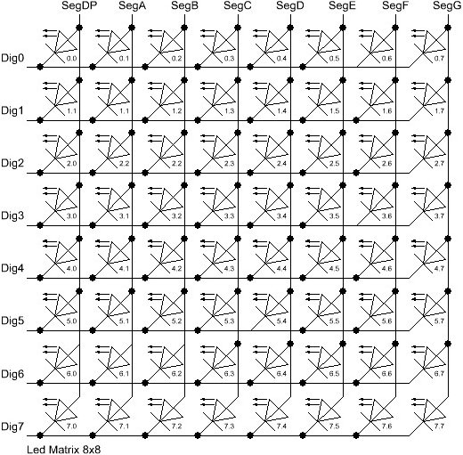
There are 8 rows (indexed from 0..7) and 8 columns (also indexed from 0..7) in the matrix. If we want to light up the LED which is located at the very right of the 3'rd row from the top, simply take the index of the Led (2.7) and use is as the row and column arguments.
Here's some code that lights up a few LEDs
//switch on the led in the 3'rd row 8'th column
//and remember that indices start at 0!
lc.setLed(0,2,7,true);
//Led at row 0 second from left too
lc.setLed(0,0,1,true);
delay(500);
//switch the first Led off (second one stays on)
lc.setLed(0,2,7,false);
setLed() is fine if you light up only a few LEDs, but if more LEDs need to be updated, it would require many lines of code. So there are two more functions in the library, that control a complete row and column with a single call.
Control all the LEDs in a row
The setRow(addr,row,value)-function takes 3 arguments. The first one is the already familiar address of our device. The second one is the row that is going to be updated and the third one the value for this row.
But how do we know which LEDs light up for a specific value? The value, a byte, uses a simple encoding where each bit set to 1 represents a lit led and an unset bit a Led switched off. Here is an example:
We want to light up the marked LEDs from the schematic...

The index for the row to be updated is 2. Now we have to set the byte-value for the LEDs to be lit. The easiest approach is to include the standard header-file <binary.h> to your sketch. Now you can write down the value in binary encoding and have an exact mapping between bits set to 1 and the LEDs to be switched on. To light up the the LEDs from the example we could simply write:
//include this file so we can write down a byte in binary encoding
#include <binary.h>

//now setting the LEDs from the third row on the first device is easy
lc.setRow(0,2,B10110000);
If for any reason you can not specify the value in binary encoding, here is a simple table that maps the decimal values of each bit to the Led it affects. The two rows at bottom give an example for how to calculate the decimal value for the example from above.
| Led 2.0 | Led 2.1 | Led 2.2 | Led 2.3 | Led 2.4 | Led 2.5 | Led 2.6 | Led 2.7 | ||
| Bit-Value | 128 | 64 | 32 | 16 | 8 | 4 | 2 | 1 | |
| On | Yes | No | Yes | Yes | No | No | No | No | |
| Row-Value | 128 | 0 | 32 | 16 | 0 | 0 | 2 | 0 | =176 (128+32+16) |
Inside your code you would use lc.setRow(0,2,176) to update this row on the first MAX72XX attached to the Arduino. As a side-effect the setRow()-call is much faster than calling setLed() in turn for each Led. So use this method wherever you can.
Here is the signature of the method :
/*
 * Set all 8 LEDs in a row to a new state
 * Params:
 * addr  address of the display
 * row   row which is to be set (0..7)
 * value each bit set to 1 will light up the corresponding Led.
 */
void setRow(int addr, int row, byte value);
Control all the LEDs in a column
What can be done for rows can likewise be done with columns. The setColumn()-method updates 8 LEDs in the vertical columns.
Here is an example.
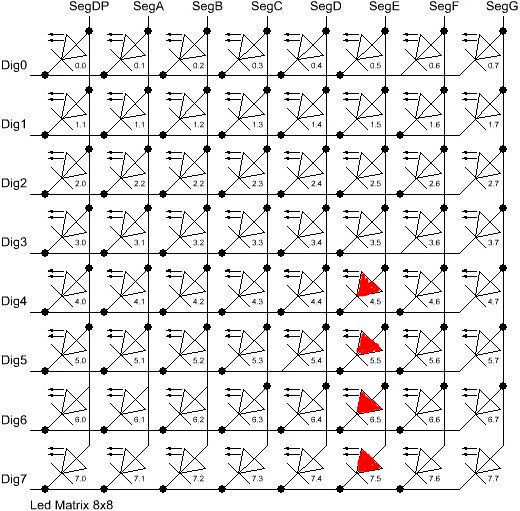
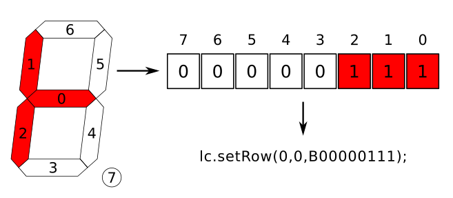
This time we want the 4 LEDs at the bottom of column 6 to be lit. We can use the the binary encoding again. Here the leftmost bit in the value refers to the Led at the top of the column:
//include this file so we can write down a byte in binary encoding
#include <binary.h>

//now setting the leds from the sixth column on the first device is easy
lc.setColumn(0,5,B00001111);
and here is the table that maps bits to the LEDs for columns:
| LED 0.5 | LED 1.5 | LED 2.5 | LED 3.5 | LED 4.5 | LED 5.5 | LED 6.5 | LED 7.5 | ||
| Bit-Value | 128 | 64 | 32 | 16 | 8 | 4 | 2 | 1 | |
| On | No | No | No | No | Yes | Yes | Yes | Yes | |
| Col-Value | 0 | 0 | 0 | 0 | 8 | 4 | 2 | 1 | =15 (8+4+2+1) |
The signature of the method is almost the same a the row-version of it:
/*
 * Set all 8 LEDs in a column to a new state
 * Params:
 * addr  address of the display
 * col   column which is to be set (0..7)
 * value each bit set to 1 will light up the corresponding Led.
 */
void setColumn(int addr, int col, byte value);
A complete example for the Led matrix functions can be found on the demo-page for the library.
A note on performance...
There is an important difference between the way the setRow()- and the setColumn()- methods update the Leds:
setRow()only needs to send a singleint-value to theMAX72XXin order to update all 8 LEDs in a row.setColumn()uses thesetLed()-method internally to update the LEDs. The library has to send 8intsto the driver, so there is a performance penalty when usingsetColumn(). You won't notice that visually when using only 1 or 2 cascaded LED boards, but if you have a long queue of devices (6..8) which all have to be updated at the same time, that could lead to some delay that is actually visible.
Controlling 7-Segment displays
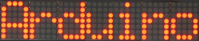
It's not the standard usage for 7-segment LEDs...
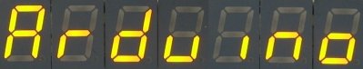
... but looks good!
Printing numbers
The most common use of 7-segment displays is to show numbers. The first function we look at, takes an argument of type byte and prints the corresponding digit on the specified column. The range of valid values runs from 0..15. All values between 0..9 are printed as digits, values between 10..15 are printed as their hexadecimal equivalent.
Any other value will simply be ignored, which means nothing will be printed. The column on the display will not be blanked, it will simply retain its last valid value. The decimal point on the column can be switched on or off with an extra argument.
Here is a small example that prints an int value (-999..999) on a display with 4 digits.
void printNumber(int v) {
    int ones;
    int tens;
    int hundreds;
    boolean negative;

    if(v < -999 || v > 999)
       return;
    if(v<0) {
        negative=true;
        v=v*-1;
    }
    ones=v%10;
    v=v/10;
    tens=v%10;
    v=v/10;
    hundreds=v;
    if(negative) {
       //print character '-' in the leftmost column
       lc.setChar(0,3,'-',false);
    }
    else {
       //print a blank in the sign column
       lc.setChar(0,3,' ',false);
    }
    //Now print the number digit by digit
    lc.setDigit(0,2,(byte)hundreds,false);
    lc.setDigit(0,1,(byte)tens,false);
    lc.setDigit(0,0,(byte)ones,false);
}
This is the prototype for the function:
/*
 * Display a (hexadecimal) digit on a 7-Segment Display
 * Params:
 * addr  address of the display
 * digit the position of the digit on the display (0..7)
 * value the value to be displayed. (0x00..0x0F)
 * dp    sets the decimal point.
 */
void setDigit(int addr, int digit, byte value, boolean dp);
The digit-argument must be from the range 0..7 because the MAX72XX can drive up to eight 7-segment displays. The index starts at 0 as usual.
Printing characters
There is a limited set of characters that make (visual) sense on a 7-segment display. A common use would be the character '-' for negative values and the 6 characters from 'A'..'F' for hex-values.
The setChar(addr,digit,value.dp)-function accepts a value of type char for the whole range of 7-bit ASCII encoding. Since the recognizable patterns are limited, most of the defined characters will be the <SPACE>-char. But there are quite a few characters that make sense on a 7-segment display.
Here is the set of printable characters:
0 1 2 3 4 5 6 7 8 9A a(prints upper case)B b(prints lower case)C c(prints lower case)D d(prints lower case)E e(prints upper case)F f(prints upper case)H h(prints upper case)L l(prints upper case)P p(prints upper case)-(the minus sign).,(lights up the decimal-point)_(the underscore)<SPACE>(the blank or space char)
For your convenience, the hexadecimal characters have also been redefined at
the character values 0x00...0x0F. If you want to mix digits and characters on the display, you can simply take the same byte argument that you would have used for the setDigit()-function and it will print the hexadecimal value.
The prototype of the function is almost the same as the one for displaying digits.
/*
 * Display a character on a 7-Segment display.
 * There are only a few characters that make sense here :
 * '0','1','2','3','4','5','6','7','8','9','0',
 * 'A','b','c','d','E','F','H','L','P',
 * '.','-','_',' '
 * Params:
 * addr	  address of the display
 * digit  the position of the character on the display (0..7)
 * value  the character to be displayed.
 * dp     sets the decimal point.
*/
void setChar(int addr, int digit, char value, boolean dp);
Any other character could be drawn with setRow() function. For example, if you want to display something which look like a lower case 't' :
Commented demos for the library
Some commented demos for the LedControl-library are on page LedControlDemos. You can also download the code for the demos from there.
Sourcecode and download
The sourcecode for the library is on GitHub
The latest binary release is always available from the LedControl Release Page
Instructions to install a library for the Arduino IDE are found here
Now create a new sketch with the following content...
#include "LedControl.h"

void setup() {}
void loop() {}
... hit the verify button and the library will be compiled and is available for all of your sketches that start with a #include "LedControl.h" line.
The Zip-File also contains 3 example sketches which are documented on the LedControlDemos page.
Known bugs
Currently none
Revision History
- May 26, 2014 Fixed an error in the
setChar()function. - Februrary 10, 2014 Updated the install instructions for the library.
- September 10, 2012 Changed the software license from LGPL to an MIT-style license.
- September 19, 2011 Uploaded new version of LedControl.zip. Release 1.0 of the Arduino IDE renamed the internal header file
WProgramm.htoArduino.h. The include statement inLedControl.hwas updated so the library compiles under pre- and post-1.0 versions of the IDE - October 14, 2008 Uploaded a new version of the LedControl.zip. The original version did not compile under arduino-0012.
- December 5, 2007 Documentation and source code is now hosted on the Arduino Playground
- June 23, 2007 First public release
Feedback
You are also welcome to send questions, objections or corrections to <e.fahle@wayoda.org>, or create an issue on the GitHub page for the library
License (The software)
The source code for this library is released under the Terms of the GNU Lesser General Public License version 2.1.
