Master Reader/Slave Sender
In some situations, it can be helpful to set up two (or more!) Arduino and Genuino boards to share information with each other. In this example, two boards are programmed to communicate with one another in a Master Reader/Slave Sender configuration via the I2C synchronous serial protocol. Several functions of Arduino's Wire Library are used to accomplish this. Arduino 1, the Master, is programmed to request, and then read, 6 bytes of data sent from the uniquely addressed Slave Arduino. Once that message is received, it can then be viewed in the Arduino Software (IDE) serial monitor window.
The I2C protocol involves using two lines to send and receive data: a serial clock pin (SCL) that the Arduino or Genuino Master board pulses at a regular interval, and a serial data pin (SDA) over which data is sent between the two devices. As the clock line changes from low to high (known as the rising edge of the clock pulse), a single bit of information - that will form in sequence the address of a specific device and a a command or data - is transferred from the board to the I2C device over the SDA line. When this information is sent - bit after bit -, the called upon device executes the request and transmits it's data back - if required - to the board over the same line using the clock signal still generated by the Master on SCL as timing.
Because the I2C protocol allows for each enabled device to have it's own unique address, and as both master and slave devices to take turns communicating over a single line, it is possible for your Arduino or Genuino board to communicate (in turn) with many devices, or other boards, while using just two pins of your microcontroller.
Hardware Required
- 2 Arduino or Genuino Boards
- hook-up wires
Circuit
Connect pin 4 (the data, or SDA, pin) and pin 5 (the clock, or SCL, pin) on the master board to their counterparts on the slave board. Make sure that both boards share a common ground. In order to enable serial communication, the master board must be connected to your computer via USB.
If powering the boards independently is an issue, connect the 5V output of the Master to the VIN pin on the slave.
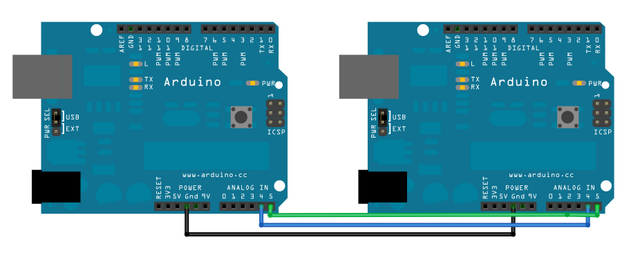
image developed using Fritzing. For more circuit examples, see the Fritzing project page
Schematic

Code
Code for Master Reader - Program for Arduino 1
// by Nicholas Zambetti <http://www.zambetti.com>
// Demonstrates use of the Wire library
// Reads data from an I2C/TWI slave device
// Refer to the "Wire Slave Sender" example for use with this
// Created 29 March 2006
// This example code is in the public domain.
#include <Wire.h>
void setup() {
Wire.begin(); // join i2c bus (address optional for master)
Serial.begin(9600); // start serial for output
}
void loop() {
Wire.requestFrom(8, 6); // request 6 bytes from slave device #8
while (Wire.available()) { // slave may send less than requested
char c = Wire.read(); // receive a byte as character
Serial.print(c); // print the character
}
delay(500);
}
Code for Slave Sender - Program for Arduino 2
// by Nicholas Zambetti <http://www.zambetti.com>
// Demonstrates use of the Wire library
// Sends data as an I2C/TWI slave device
// Refer to the "Wire Master Reader" example for use with this
// Created 29 March 2006
// This example code is in the public domain.
#include <Wire.h>
void setup() {
Wire.begin(8); // join i2c bus with address #8
Wire.onRequest(requestEvent); // register event
}
void loop() {
delay(100);
}
// function that executes whenever data is requested by master
// this function is registered as an event, see setup()
void requestEvent() {
Wire.write("hello "); // respond with message of 6 bytes
// as expected by master
}
See Also
- Wire.begin()
- Wire.RequestFrom()
- Wire.receive()
- Wire.send()
- Wire.onRequest()
- Wire Library – Your reference for the Wire Library.
- DigitalPotentiometer - How to control an Analog Devices AD5171 Digital Potentiometer.
- SFRRanger_reader - How to read an ultra-sonic range finder interfaced via the I2C.
- Master Writer/Slave receiver - Two Arduino are programmed to communicate in a Master Writer/Slave Receiver configuration via the I2C.
Last revision 2018/05/17 by SM
