Stepper Speed Control
Stepper motors, due to their unique design, can be controlled to a high degree of accuracy without any feedback mechanisms. The shaft of a stepper, mounted with a series of magnets, is controlled by a series of electromagnetic coils that are charged positively and negatively in a specific sequence, precisely moving it forward or backward in small "steps".
There are two types of steppers, Unipolars and Bipolars, and it is very important to know which type you are working with. For each of the motors, there is a different circuit. The example code will control both kinds of motors. See the unipolar and bipolar motor schematics for information on how to wire up your motor.
In this example, a potentiometer (or other sensor) on analog input 0 is used to control the rotational speed of a stepper motor using the Arduino Stepper Library. The stepper is controlled by with digital pins 8, 9, 10, and 11 for either unipolar or bipolar motors.
The Arduino or Genuino board will connect to a U2004 Darlington Array if you're using a unipolar stepper or a SN754410NE H-Bridge if you have a bipolar motor.
For more information about the differences of the two types, please take a look at Tom Igoe's page on stepper motors.
Hardware Required
- Arduino or Genuino Board
- 10k ohm potentiometer
- stepper motor
- U2004 Darlington Array (if using a unipolar stepper)
- SN754410ne H-Bridge (if using a bipolar stepper)
- power supply appropriate for your particular stepper
- hook-up wires
- breadboard
Circuits
Below you'll find circuits for both unipolar and bipolar steppers. In either case, it is best to power your stepper motors from an external supply, as they draw too much to be powered directly from your Arduino board.
In both circuits, connect a 10k pot to power and ground, with it's wiper outputting to analog pin 0.
Note: Both circuits below are four wire configurations. Two wire configurations will not work with the code provided.
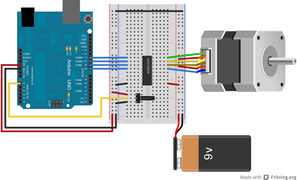
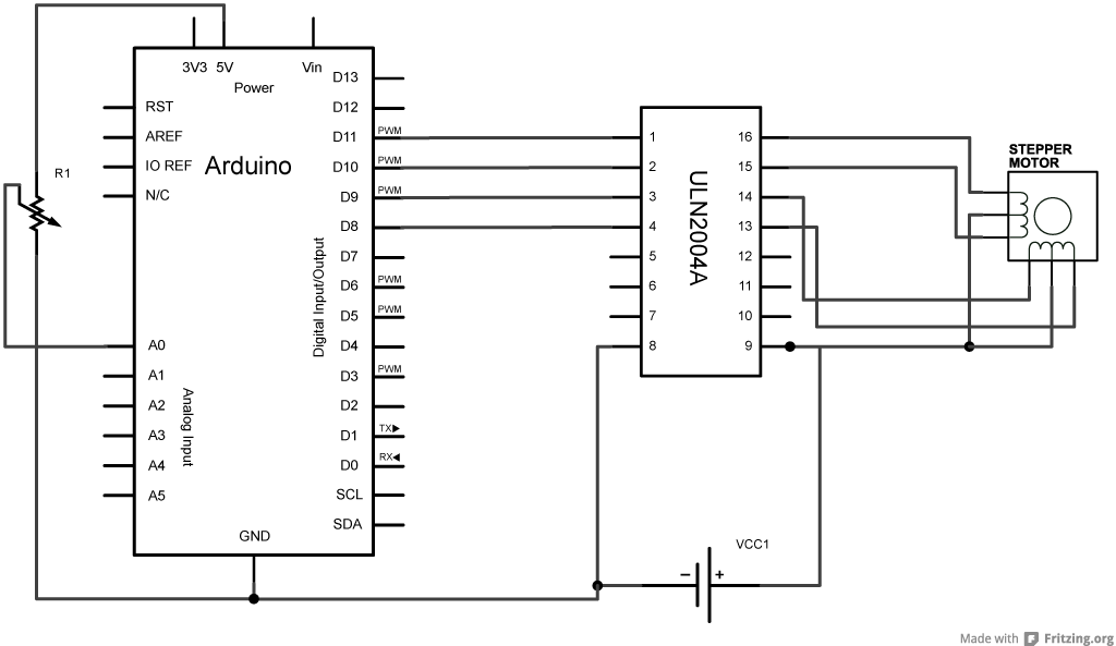
Unipolar Stepper Circuit and schematic
|
Show images for the unipolar circuit and schematicShow images for the unipolar circuit and schematic |
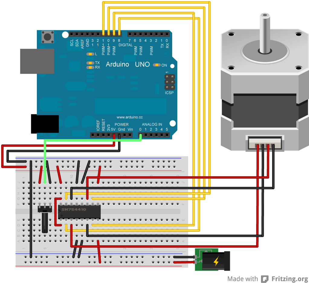
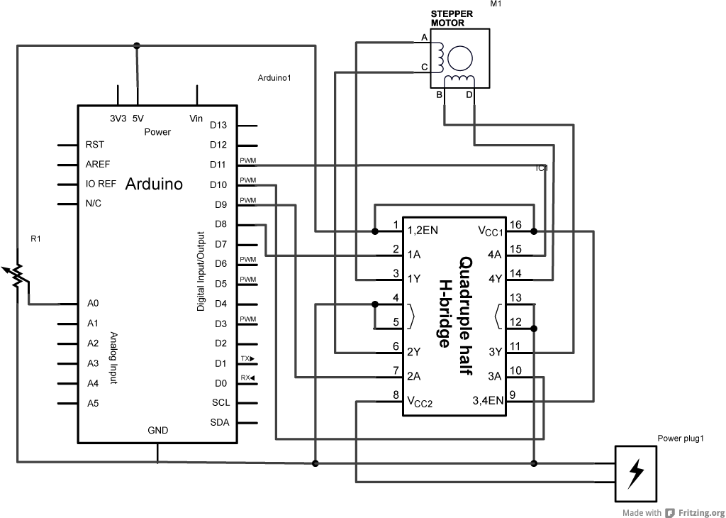
Bipolar Stepper Circuit and schematic
|
Show images for the bipolar circuit and schematicShow images for the bipolar circuit and schematic |
Code
For both unipolar and bipolar steppers
Stepper Motor Control - speed control
This program drives a unipolar or bipolar stepper motor.
The motor is attached to digital pins 8 - 11 of the Arduino.
A potentiometer is connected to analog input 0.
The motor will rotate in a clockwise direction. The higher the potentiometer value,
the faster the motor speed. Because setSpeed() sets the delay between steps,
you may notice the motor is less responsive to changes in the sensor value at
low speeds.
Created 30 Nov. 2009
Modified 28 Oct 2010
by Tom Igoe
*/
#include <Stepper.h>
const int stepsPerRevolution = 200; // change this to fit the number of steps per revolution
// for your motor
// initialize the stepper library on pins 8 through 11:
Stepper myStepper(stepsPerRevolution, 8, 9, 10, 11);
int stepCount = 0; // number of steps the motor has taken
void setup() {
// nothing to do inside the setup
}
void loop() {
// read the sensor value:
int sensorReading = analogRead(A0);
// map it to a range from 0 to 100:
int motorSpeed = map(sensorReading, 0, 1023, 0, 100);
// set the motor speed:
if (motorSpeed > 0) {
myStepper.setSpeed(motorSpeed);
// step 1/100 of a revolution:
myStepper.step(stepsPerRevolution / 100);
}
}
See also
- Stepper myStepper = Stepper(steps, pin1, pin2, pin3, pin4)
- stepper.setSpeed()
- stepper.step()
- Stepper library reference
- MotorKnob - Moves the shaft according to the position of the knob of a potentiometer.
- StepperOneRevolution - Turn the shaft one revolution clockwise and one counterclockwise.
- StepperOneStepAtATime - Single stepping to check the proper wiring of the motor.
Last revision 2018/08/23 by SM
