Examples > TFT
TFT EtchASketch

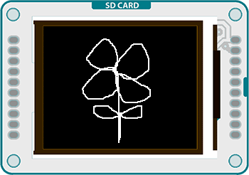
This example for the Arduino TFT draws a white line on the screen, based on the position of 2 potentiometers. If you press a momentary button, the screen will erase.
Hardware Required
- Arduino Uno
- Arduino TFT screen
- breadboard
- hookup wire
- two 10-kilohm potentiometers
- momentary switch
- 10-kilohm resistor
Circuit
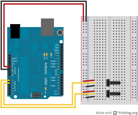
Connect power and ground to the breadboard.
Show me how to do thatShow me how to do that
Place the potentiometers on the breadboard. On each pot, connect one side to ground, and the other to power. Connect the middle pin of one potentiometer to A0, the other one to A1.
Show me how to do thatShow me how to do that
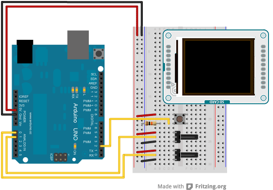
Put a switch across the center of the breadboard. Connect one end to power, the other end to the Arduino digital pin 2. Connect the same pin to ground through a 10-kilohm pull-down resistor
Show me how to do thatShow me how to do that
Connect the screen to the breadboard. The headers on the side of the screen with the small blue tab and arrow should be the ones that attach to the board. Pay attention to the orientation of the screen, in these images, it is upside down.
Show me how to do thatShow me how to do that
Connect the BL and +5V pins to power, and GND to ground. Connect CS-LD to pin 10, DC to pin 9, RESET to pin 8, MOSI to pin 11, and SCK to pin 13. If uyou're using a Leonardo, you'll be using different pins. see the getting started page for more details.
Show me how to do thatShow me how to do that
Code
To use the screen you must first include the SPI and TFT libraries.
#include <TFT.h>
Define the pins you're going to use for controlling the screen, and create an instance of the TFT library named TFTscreen. You'll reference that object whenever you're working with the screen.
#define dc 9
#define rst 8
TFT TFTscreen = TFT(cs, dc, rst);
Set up the cursor's x & y position. In the example, it starts in the center of the screen; determined by dividing the height and width of the screen by 2. Create a named pin for your erase switch.
int yPos = LCDscreen.height()/2;
int erasePin = 2;
In setup(), after declaring the erase pin as an input, initialize the display and clear the screen's background.
pinMode(erasePin, INPUT);
TFTscreen.begin();
TFTscreen.background(0,0,0);
}
Read the values of the pots and map them to smaller numbers.
{
int xValue = analogRead(A0);
int yValue = analogRead(A1);
xPos = xPos + (map(xValue, 0, 1023, 2, -2));
yPos = yPos + (map(yValue, 0, 1023, -2, 2));
You'll want to keep the cursor from moving offscreen with a few if() statements before you draw the point.
(xPos = 159);
}
if(xPos < 0){
(xPos = 0);
}
if(yPos > 127){
(yPos = 127);
}
if(yPos < 0){
(yPos = 0);
}
TFTscreen.stroke(255,255,255);
TFTscreen.point(xPos,yPos);
Finally, check the button. If it is being pressed and is HIGH, clear the screen with background().
TFTscreen.background(0,0,0);
}
delay(33);
}
The complete sketch is below :


