Arduino/Genuino 101 CurieIMU Orientation Visualiser
This tutorial demonstrates how to make use the Genuino 101's onboard 6-axis accelerometer/gyro to read the X, Y, and Z values of both the accelerometer and the gyroscope. While the gyroscope is able to determine the orientation of the board, the accelerometer measures the angular velocity of the board. Together, the accelerometer and the gyroscope form an Inertial Monitoring Unit (IMU) which can be used to precisely identify the orientation of the board. Madgwick's filter algorithm is used in this example to calculate quarternions from the 6 axes' values. The quarternions are then used to calculate Euler angles Pitch, Yaw, and Roll, which are received by Processing and used to control the rotation of an object around the X, Y and Z axes.
Hardware Required
The CurieIMU library uses the IMU (accelerometer + gyroscope) built into the Genuino/Arduino 101.
Instructions
- Set up the Arduino software (IDE) as described in Getting Started with Arduino 101.
- Connect the 101 to your computer.
- Launch the Arduino software (IDE) and select Arduino/Genuino 101 from the Tools > Board menu.
- Install the Madgwick library from library manager. To do this, open the Arduino Software (IDE), go to "Sketch -> Include Library -> Manage Libraries". There you can search 'Madgwick' and install the library directly from there. Please see the libraries installation guide for a more detailed explanation on installing and importing libraries.
- Download and Launch the Processing software and create a file with the Processing code shown below.
- Change the Serial port to the one that your 101 is using (see "Processing Sketch" section).
- Upload the example contained in the Madgwik library called Visualizer101 to your 101, making sure that the board is flat and stationery so it can perform the calibration accurately.
- After a few seconds, run the Processing sketch, adjust the orientation of your board, and watch as the Processing sketch gives a visualization of your board. The Pocessing is contained in the "extras" folder of the Madgwick library.
The Circuit
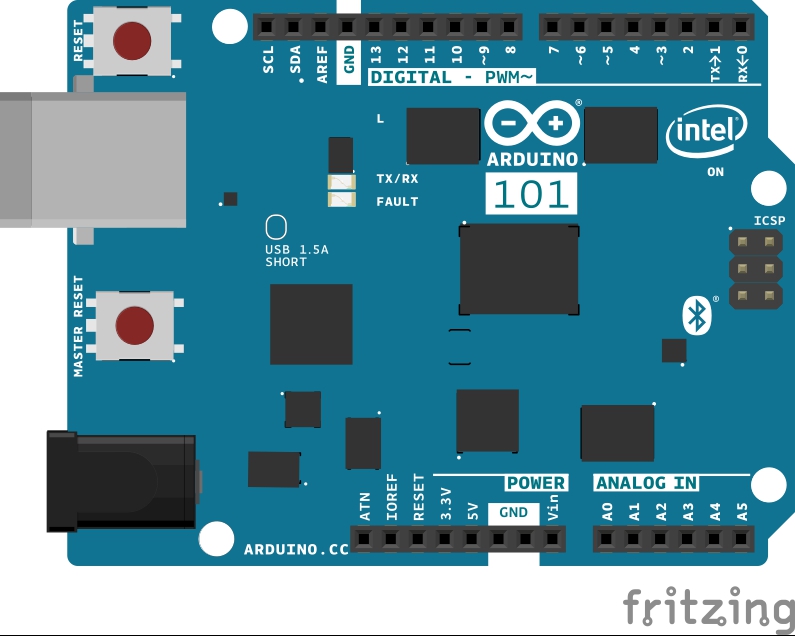
image developed using Fritzing.
How it works
The Madgwick filter algorithm is open-source and is well documented in Madgwick's information and reports. The Madgwick filter algorithm was developed by Sebastian Madgwick during his Ph.D. in 2010 and is designed to be computationally inexpensive and efficient even at low sampling rates. The algorithm takes raw values from a gyroscope and accelerometer, and uses them to return four quaternions, which are 4-dimensional numbers which contain x, y, and z values to represent the axis around which rotation occurs, as well as a ω value which represents the value of rotation which occurs around the same axis. These quaternions can be used to calculate the Euler angles pitch, yaw, and roll; three angles used to describe the orientation of a rigid body in terms of x,y, and z as presented by Leonhard Euler in the 1700s. The equations (7) (8) (9) in Madgwick's Report are used to calculate the values for pitch, roll, and yaw, and their functions are included within the library.
We can create a 3D representation of the Arduino/Genuino 101's onboard IMU in Processing, which will move as the board does. This is achieved with the values for Euler angles pitch, roll and yaw obtained by the Madgwick filter algorithm. These values can then be sent via Serial to Processing and used as angle arguments for Processing's to compute the position of the Arduino 3D model using the methods: applyMatrix(), https://processing.org/reference/pushMatrix_.htmlpushMatrix, and popMatrix() functions.
Arduino Sketch
The sketch uses functions inside the CurieIMU library to get the data from the accelerometer/gyro.
In order to see a 3D representation in Processing, the Arduino sketch must incorporate two main functionalities; using the IMU data and algorithm to calculate yaw, pitch, and roll values, and enabling serial communication in a handshake fashion in order to send those values to Processing.
First, we must create a Madgwick object to access the functions from the Madgwick class in the library. Here, we call it filter:
setup() function we perform a preliminary configuration of the CurieIMU, by setting the sample rate of the acelerometer and the gyro and the filter to 25Hz:
CurieIMU.setGyroRate(25);
CurieIMU.setAccelerometerRate(25);
filter.begin(25);
CurieIMU.setGyroRange(250);
loop() function we will need to send a sample according to the sample rate we set for the CurieIMU reading:
// convert from raw data to gravity and degrees/second units
ax = convertRawAcceleration(aix);
ay = convertRawAcceleration(aiy);
az = convertRawAcceleration(aiz);
gx = convertRawGyro(gix);
gy = convertRawGyro(giy);
gz = convertRawGyro(giz);
pitch = filter.getPitch();
heading = filter.getYaw();
As seen in the code, the gyroscope values have been scaled down by a variable factor so that they fit into a range which works well with the algorithm. Without this scaling, the values which are inputted to the function are too high and the visualization of the movement of the board becomes very sensitive to small changes of the 101's position, interpreting a slight change as a great change and causing the 'virtual' board to spin.
The full code can be found at the bottom of the page.
Note that the serial prints for gx,gy,gz,ax,az,ay are left in loop in comments for debugging and must be commented whilst communicating with Processing.
Processing Sketch
If you haven't already, the first thing to do is to download the latest version of Processing from processing.org. Processing is a language similar to Arduino which allows the user to draw dynamic imagery in the familiar void setup() and void loop() structure. For more information on using Processing, please visit their Getting Started guide.
The processing code receives incoming data from the serial port which is parsed and assigned to floats yaw, pitch, and roll, which are then used to compute the transformation matrix which moves the 3D model of the Arduino board.
To enable Processing to read from the same port that Arduino is sending to, myPort needs to be changed to your serial port's name. In setup(), this is the Second parameter of Serial.
and uncomment of the lines corresponding to your OS:
myPort = new Serial(this, "/dev/ttyACM0", 9600); // Linux
myPort = new Serial(this, "/dev/cu.usbmodem1217321", 9600); // Mac
You must replace the port string with the correct name for your COM port.
If in doubt, you can print a list of your available serial ports in a separate sketch to determine this name.
The function serialEvent() is then used to receive and parse data.
{
int newLine = 13; // new line character in ASCII
String message;
do {
message = myPort.readStringUntil(newLine); // read from port until new line
if (message != null) {
String[] list = split(trim(message), " ");
if (list.length >= 4 && list[0].equals("Orientation:")) {
yaw = float(list[1]); // convert to float yaw
pitch = float(list[2]); // convert to float pitch
roll = float(list[3]); // convert to float roll
}
}
} while (message != null);
}
Code
Arduino Code
#include <MadgwickAHRS.h>
Madgwick filter;
unsigned long microsPerReading, microsPrevious;
float accelScale, gyroScale;
void setup() {
Serial.begin(9600);
// start the IMU and filter
CurieIMU.begin();
CurieIMU.setGyroRate(25);
CurieIMU.setAccelerometerRate(25);
filter.begin(25);
// Set the accelerometer range to 2G
CurieIMU.setAccelerometerRange(2);
// Set the gyroscope range to 250 degrees/second
CurieIMU.setGyroRange(250);
// initialize variables to pace updates to correct rate
microsPerReading = 1000000 / 25;
microsPrevious = micros();
}
void loop() {
int aix, aiy, aiz;
int gix, giy, giz;
float ax, ay, az;
float gx, gy, gz;
float roll, pitch, heading;
unsigned long microsNow;
// check if it's time to read data and update the filter
microsNow = micros();
if (microsNow - microsPrevious >= microsPerReading) {
// read raw data from CurieIMU
CurieIMU.readMotionSensor(aix, aiy, aiz, gix, giy, giz);
// convert from raw data to gravity and degrees/second units
ax = convertRawAcceleration(aix);
ay = convertRawAcceleration(aiy);
az = convertRawAcceleration(aiz);
gx = convertRawGyro(gix);
gy = convertRawGyro(giy);
gz = convertRawGyro(giz);
// update the filter, which computes orientation
filter.updateIMU(gx, gy, gz, ax, ay, az);
// print the heading, pitch and roll
roll = filter.getRoll();
pitch = filter.getPitch();
heading = filter.getYaw();
Serial.print("Orientation: ");
Serial.print(heading);
Serial.print(" ");
Serial.print(pitch);
Serial.print(" ");
Serial.println(roll);
// increment previous time, so we keep proper pace
microsPrevious = microsPrevious + microsPerReading;
}
}
float convertRawAcceleration(int aRaw) {
// since we are using 2G range
// -2g maps to a raw value of -32768
// +2g maps to a raw value of 32767
float a = (aRaw * 2.0) / 32768.0;
return a;
}
float convertRawGyro(int gRaw) {
// since we are using 250 degrees/seconds range
// -250 maps to a raw value of -32768
// +250 maps to a raw value of 32767
float g = (gRaw * 250.0) / 32768.0;
return g;
}
Processing Code
Serial myPort;
float yaw = 0.0;
float pitch = 0.0;
float roll = 0.0;
void setup()
{
size(600, 500, P3D);
// if you have only ONE serial port active
myPort = new Serial(this, Serial.list()[0], 9600); // if you have only ONE serial port active
// if you know the serial port name
//myPort = new Serial(this, "COM5:", 9600); // Windows
//myPort = new Serial(this, "/dev/ttyACM0", 9600); // Linux
//myPort = new Serial(this, "/dev/cu.usbmodem1217321", 9600); // Mac
textSize(16); // set text size
textMode(SHAPE); // set text mode to shape
}
void draw()
{
serialEvent(); // read and parse incoming serial message
background(255); // set background to white
lights();
translate(width/2, height/2); // set position to centre
pushMatrix(); // begin object
float c1 = cos(radians(roll));
float s1 = sin(radians(roll));
float c2 = cos(radians(pitch));
float s2 = sin(radians(pitch));
float c3 = cos(radians(yaw));
float s3 = sin(radians(yaw));
applyMatrix( c2*c3, s1*s3+c1*c3*s2, c3*s1*s2-c1*s3, 0,
-s2, c1*c2, c2*s1, 0,
c2*s3, c1*s2*s3-c3*s1, c1*c3+s1*s2*s3, 0,
0, 0, 0, 1);
drawArduino();
popMatrix(); // end of object
// Print values to console
print(roll);
print("\t");
print(pitch);
print("\t");
print(yaw);
println();
}
void serialEvent()
{
int newLine = 13; // new line character in ASCII
String message;
do {
message = myPort.readStringUntil(newLine); // read from port until new line
if (message != null) {
String[] list = split(trim(message), " ");
if (list.length >= 4 && list[0].equals("Orientation:")) {
yaw = float(list[1]); // convert to float yaw
pitch = float(list[2]); // convert to float pitch
roll = float(list[3]); // convert to float roll
}
}
} while (message != null);
}
void drawArduino()
{
/* function contains shape(s) that are rotated with the IMU */
stroke(0, 90, 90); // set outline colour to darker teal
fill(0, 130, 130); // set fill colour to lighter teal
box(300, 10, 200); // draw Arduino board base shape
stroke(0); // set outline colour to black
fill(80); // set fill colour to dark grey
translate(60, -10, 90); // set position to edge of Arduino box
box(170, 20, 10); // draw pin header as box
translate(-20, 0, -180); // set position to other edge of Arduino box
box(210, 20, 10); // draw other pin header as box
}
